

Analysis of Negative Impacts of Software Based VDA FMEA Methodology
In response to the “The Case of the AIAG-VDA DFMEA” article written by Richard Harpster and published on January 31, 2018 by Quality Digest, Mike Bucala from Daimler Trucks North America and member of the AIAG-VDA Handbook committee wrote:
“Your article concludes that the team should have started with (Excel-based) AIAG 4th Edition methods, and (by inference) expected the Europeans to modify their software-based methods to conform to it. This in an unrealistic expectation.”
The software based VDA FMEA methodology forms the core of the proposed AIAG-VDA FMEA Handbook. Following is a description of several but not all of the software based VDA methodology requirements and functions that significantly decrease the efficiency of DFMEA and PFMEA implementation while severely reducing the effectiveness of the DFMEA and PFMEA as risk management tools.
| No | VDA Software Requirement and/or Function Description | Negative Impact on DFMEA/PFMEA Process |
|---|---|---|
| 01 | A DFMEA and Design Verification Plan is created for every Element in Structure Tree except for Element Characteristics. | The Design FMEA is a risk assessment of releasing the hardware specifications and/or software code in their current form for manufacture. The Design FMEA is used to drive the contents of the Design Verification Plan which when properly used determines the occurrence rating in the Design FMEA.
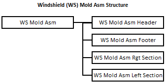
When dealing with complex products there can be multiple design groups. When multiple groups are involved, a Design FMEA and corresponding Design Verification Plan must be performed by each group to perform a risk assessment of releasing the hardware specifications and/or software code that each group is responsible for. If there is a single design group only a single Design FMEA and Design Verification are required. The VDA Software FMEA Method does not support the creation of Design FMEAs and Design Verification Plans based on Design Responsibility. When using the VDA Software FMEA Method, an individual Design FMEA and Design Verification Plan must be created for the product as a whole and every sub-assembly and component in the product that is to be included in the Design FMEA scope. The number of Design Groups has no impact on the number of Design FMEAs and Design Verification Plans created when using the VDA Software FMEA Method. The increase in required quantity of DFMEAs due to the use of the VDA Software FMEA Method can be considerable. It is not uncommon that well over 100 Design FMEAs and supporting Design Verification Plans must be created when a single Design FMEA and Design Verification was all that was required to manage risk effectively using the AIAG 4th Edition FMEA Method. The following Structure Tree would be created using the VDA Software FMEA Method for a Windshield (WS) Mold Asm which consists of 4 extrusions (Header, Footer, Rgt Section, Left Section) joined at the corner via molding. The VDA Software FMEA Method would require the creation of 5 DFMEAs and associated DVPs (one for each element of the Structure Tree) to perform a complete design risk assessment of the WS Mold Asm. If the WS Mold Asm design risk management was performed using the AIAG 4th Edition FMEA Method, 1 DFMEA and 1 DVP would be required. Impact of VDA Software FMEA Method on FMEA Process: |
| 02 | When performing a DFMEA, the entry of a Failure Cause of improperly set Product Component Specification requires entry of a Component Function and Failure first. | The root cause of design failures and consequently design risk exposure is improperly defined hardware specification(s) or software code. If one wishes to reduce the design risk in the product, hardware specifications and/or software code must be modified.
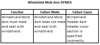
Let us assume the product is the Windshield (WS) Mold Asm discussed in issue 01. Let us also assume the Windshield Mold DFMEA addresses the requirement of mating and sealing with the Window. Let us also assume that a possible cause of not mating with the Window is the WS Mold Asm Header cross-section being improperly specified. Using the AIAG 4th Edition FMEA method, the Function, Failure Mode, and Failure Cause found in the Windshield Mold Assembly DFMEA would look as follows:
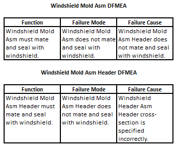
The VDA Software FMEA Method requires that all hardware component specifications be linked to a failure of the hardware component before they are used as failure causes in a DFMEA. This requires modifications to the Windshield Asm DFMEA above and creation of an additional DFMEA for the Windshield Asm Header. Following is the modified Windshield Asm DFMEA and Windshield Asm Header DFMEA:
Impact of VDA Software FMEA Method on FMEA Process: |
| 03 | When performing a DFMEA, internally defined Functions/ Requirements must be defined for all Elements in the Structure Tree for a product. | The VDA Software FMEA Method requires that every product design requirement be decomposed to internally defined verifiable design function/requirements for every sub-assembly and component identified in the scope of the DFMEA that is involved in meeting the product level design function/requirement. The definition of product level design requirements to sub-assemblies and component level design requirements is not required to perform a proper design risk assessment.
The customer does not purchase the performance of the individual sub-assemblies and components. They purchase the performance of the product. Although a design engineer may develop a set of internal sub-assembly or component design requirements to aid in the design process, the engineer must never forget that the customer is purchasing the product design requirements. If a mistake is made in the translation of a product design requirement that the customer is purchasing to engineering defined internal design requirement(s), a product can be created where the sub-assemblies and components pass all the required design verification and the product fails to meet the customer’s product level design requirements. The software based VDA DFMEA methodology has no method for detecting improperly defined internal design function/requirements or managing risk due to their incorrect definition. In thirty years of reviewing DFMEAs, the improper definition of product level function/design requirements was the most common mistake found. The software based VDA DFMEA method will expose companies to a geometric increase in this type of mistake. If the AIAG-VDA FMEA committee insists on using the current VDA FMEA Software Method, an additional level of “design requirement” risk assessment must be added for every sub-assembly and component identified in the scope of the DFMEA. A Design Validation Plan must be included in the risk assessment to determine the probability of customer exposure to harm due to improperly defined internal sub-assembly and component design requirements. The current VDA software in existence will have to be modified to support the additional risk assessment. Even when done correctly, the required translation of product level design requirements to sub-assembly and component level design requirements is very often unnecessary. Why must an engineer be required to document that the function of a “Seal” is to seal or the function of a “Screw” is to attach to perform a design risk assessment? One of the biggest complaints engineers have about Design FMEAs is the time it takes to perform them. Impact of VDA Software FMEA Method on FMEA Process: |
| 04 | When performing a DFMEA, the Failure of the Element below the Focus Element is entered in the Failure Cause Column of the Focus Element DFMEA. | Unless the Element below the Focus Element is a Characteristic, this software based VDA methodology functionality results in an Element Failure Mode being entered as a Failure Cause in the DFMEA. This is a non-root cause of the Function Element Failure Mode. (Note: See Issue 2 above for example.) When a non-root cause is entered in the DFMEA, that line of the DFMEA cannot be used for risk management.
Impact of VDA Software FMEA Method on FMEA Process: |
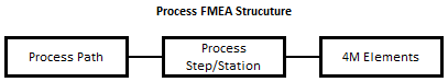
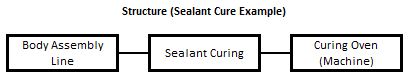
| 05 | When performing a PFMEA, the Failure of the 4M Element to meets it Function is entered in the Failure Mode column of the Function Element (Process Step) PFMEA. | When creating a Process FMEA, the VDA PFMEA METHOD uses a three level Structure.
The first level has one Element. It is the Process Path. The second level has one Element for each of the Process Steps in the Process Path. The second level Elements are known as Focus Elements. The VDA PFMEA METHOD creates a PFMEA for each Focus Element in the second level. The third level defines the 4M Elements (Man, Machine, Material, Environment) used by the Process Step. Following is an example of a Structure Tree that would be created to perform a PFMEA on a Sealant Curing Station.
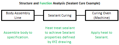
The next step in the VDA PFMEA METHOD is to create a Function Analysis. Functions for each of the Elements in the Structure Tree must be defined. Following is an example of a Function Analysis Tree for the Sealant Curing Station PFMEA.
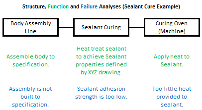
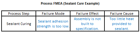
When generating the Sealant Curing PFMEA using information from Structure and Failure Analyses, the VDA software places the Sealant Curing Element Failure in the Failure Mode Column, the Body Assembly Line Element Failure in the Effects column and the Curing Oven Element Failure in the Failure Cause Column.
The VDA PFMEA METHOD defines the Failure Cause of the Failure Mode “Sealant adhesion strength is too low” as how the Curing Oven failed to meet its function (“Too little heat provided to sealant.”). The root cause of the Failure Mode “Sealing adhesion strength is too low” is not “how” but “why” the Curing Oven failed to meet its function. Example of root causes would be “Curing Oven Temperature Controller is out of calibration” and “Curing Oven Temperature Setting is set too low”. These are the root causes of “Too little heat provided to the sealant” and consequently the root causes of “Sealant adhesion strength is too low”. Impact of VDA Software FMEA Method on FMEA Process: The definition of root causes in the PFMEA is critical to the proper construction of the Process Control Plan. During the AIAG Software Summit, Mr. Cachat provided information from a 2018 study on IATF 16949 Audit Findings. He stated that “surprisingly Control Plans had 400 major findings and 6000 minor findings”. Why would the AIAG want to introduce a new PFMEA methodology that will severely increase the current major Control Plan problem? |
| 06 | When performing a PFMEA, the Failure of the Focus Element to meets it Function is entered in the Failure Mode column. | A process step can create objectionable conditions of the manufactured product that have nothing to do with the Function of the process step. These conditions can take on many forms including but not limited to contamination, material changes and dimensional changes. To capture these failures one would have to enter “negative functions” in the Function Analysis.
Impact of VDA Software FMEA Method on FMEA Process: |
“Harpco breaks down the barriers and corrects the pitfalls so companies can reap the full benefits of FMEA. Classroom training not only properly teaches FMEA, but participants actually build their business’s FMEA as they go and are often blown away by how much work got accomplished. Harpco Systems has become known as the Modern FMEA for a reason. Its structured, simplified and sustainable.”
 Chris Follis, Regal Beloit Director of Quality
“We used QPlus to achieve Q1 and ISO 16949 successfully at the Ford Motor Co. Monroe BAO Plant. The software promoted linked documentation that prevented issues at internal and external audits. Assured the quality documents at the operations production level had all relevant and concurrent information that was reviewed in the program files. QPlus allowed the program members to create a baseline “Hot End Exhaust” database that produced linked documentation from the DFMEA to the production visual aids the operators used to perform correctly.”
 Chris Norton, Ford Engineering Manager
“Harpco’s training is first rate and helps develop new ways of thinking about the importance of creating proper specifications early. Separately, I’ve seen firsthand the effectiveness of using their approach in problem solving, helping to advance problems that had reached a stall using traditional methods.”
 Todd Gross, VP of Global Quality
“We were very fortunate to work with Rich Harpster and his team as we improved our DFMEA process at Calsonic. There is no better teacher, coach, implementer than Rich when it comes to creating a knowledge base for engineers to use in creating part specs to assure that products meet the customer’s requirements. Rich teaches the basics, then he accelerates the FMEA process so that requirements and specs are related in a database that can be continually updated.”
 Marv Beasley, Calsonic Director of Engineering
“I would like to thank Harpco Systems for the help, advice and frankly the education in how to design, develop, source and manufacture new to world products.”