

The Case Against The AIAG-VDA Process FMEA
In a previous article “The Case Against the AIAG-VDA DFMEA” proof was provided on why adoption of the proposed Handbook DFMEA methodology would result in the implementation of a DFMEA methodology that is considerably less effective and much more inefficient than the current the AIAG 4th Edition FMEA Manual DFMEA methodology. The purpose of this paper is to show that the adoption of the proposed AIAG-VDA Handbook PFMEA methodology would result in similar reductions in effectiveness and increases in inefficiencies when compared to the existing AIAG 4th Edition PFMEA process.
Purpose of a Process FMEA
All manufacturing processes have process requirements that must be met. The process requirements include but are not limited to producing within specification product, producing product within a specified time and not exposing workers to injury. Risk exposure occurs whenever a process does not meet a process requirement. Due to the complexity of processes and the products which they produce, the potential sources of risk are so numerous that companies do not have the time and resources to work on them all. They must be prioritized.
When done properly, the Process FMEA is a structured risk assessment of the adequacy of the manufacturing process in meeting its process requirements. The PFMEA allows the manufacturing personnel to identify the potential causes of process failure that pose the greatest risk so actions can be taken to reduce the probability of them occurring to a level that is acceptable to both the customer and company.
Using the AIAG PFMEA method to manage risk
The following PFMEA covers use of a curing oven to cure sealant that has been applied to a car body. If the sealant is under-cured it may not adhere to the car body thus resulting in water intrusion and corrosion. If the sealant is over-cured, Hydrochloric Acid (HCL) can leach from the sealant causing it to break down and become brittle. The concern is that the current Curing Oven Program Temperature Setting may be incorrect. The PFMEA will be used to define the potential risk.
Following is a properly constructed PFMEA using the AIAG 4th Edition PFMEA method addressing the curing oven computer program oven temperature setting.
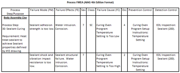
The PFMEA accomplishes the risk assessment of the current Curing Oven Program Temperature Setting in the following manner:
- The first step of the PFMEA process is to define the process flow. The Process Step/Purpose column is used to capture each step of the process and to define the process requirement(s) the process step is attempting to meet (“Heat treat sealant to achieve required Sealant properties defined by XYZ drawing”).
- The Failure Mode column is used to capture the two ways in which the process can fail to meet the requirement. Two defects are identified (“Sealant adhesion strength is too low.”, “Sealant shock and vibration resistance is too low.
- A description of the harm that can be experienced when the failure occurs is provided in the “Failure Effects (FE)” column (“Water Intrusion. Corrosion.”).
- A numerical rating is placed in the “Sev” (aka “Severity”) column that corresponds to the severity of harm described in the “Failure Effects” column (“7”).
- The potential cause of the defect in the FM column is entered in the “Failure Cause (FC)” column (“Curing Oven program temperature setting is too low.”). To use the PFMEA to manage risk, the FC must always be a root cause.
- The method(s) that will be used to reduce the probability of the FC from occurring or prevent the process from running when the FC is present, is known as a “Prevention Control” (“Curing Oven Program Setup Instructions: Temperature Setting”).
- A determination of the probability of the FM occurring due to the FC must be made. A numerical rating equivalent to the probability is entered in the “OCC” or “Occurrence” column. One common mistake is to use the probability of the FC to determine the “OCC” rating. The presence of a FC does not guarantee the creation of a FM.
- The “Sev” and “Occ” are looked up in a Risk Matrix that has symbols corresponding to the level of risk indicated by the “Sev” and “Occ” ratings. The appropriate risk level symbol is placed in the “Class” column (“SC”). In the example PFMEA, the probability of experiencing low sealant adhesion strength due to the current Curing Oven Program Oven Temperature Setting being too low is considered unacceptable.
Using the proposed handbook PFMEA methodology to manage risk
In the AIAG-VDA Handbook PFMEA Method, the processing line name, process steps, process requirements, failure modes, effects and causes are not entered directly into the PFMEA as they are in the AIAG 4th Edition FMEA. They are derived from a Structure Analysis, Function Analysis and Failure Analysis.
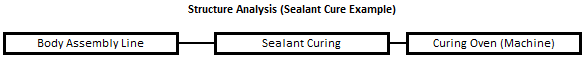
The Structure Analysis is comprised of the Process Item, Process Step(s) and Process Work Element(s). The Process Item is the name of the processing line that the PFMEA will be performed on. The Process Step(s) are the process steps that make up the processing line. The next step in creating the Structure Analysis is to identify the Process Work Elements for each Process Step. The Process Work Elements are categories of failure causes. There are six different categories. If you are familiar with Ishikawa Diagrams, the categories are the six Ishikawa Diagram cause category types: Machine, Man, Milieu (Environment), Material (Indirect), Method and Measurement. As an example, the Process Work Element for the example PFMEA would be “Curing Oven (Machine)”. If an operator was referenced in our PFMEA example, another Process Work Element would be “Operator (Man)”.
Following is the structure analysis for the PFMEA example provided.
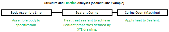
The next step is to create a Function Analysis. The Function Analysis is created by defining the functions of the Process Item, Process Step(s) and Process Work Element(s). The creator of the Function Analysis must define functions for each of the categories of causes when defining the functions for the Process Work Elements
Following is the function analysis for the PFMEA example for the “Failure Modes” that can be covered.
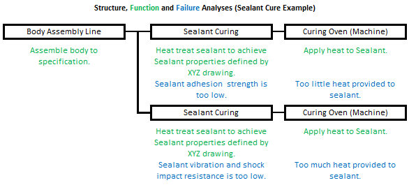
Once the Function analysis has been created the next step is to construct the Failure analysis. The Failure analysis contains the failures for the Process Item, Process Step and Process Work Element functions.
Following is the failure analysis for the PFMEA example.
The AIAG-VDA PFMEA form was developed to support the implementation of the Structure Analysis, Function Analysis, Failure Analysis and PFMEA. Consequently, there is additional information in the Handbook PFMEA form that is not found in the AIAG 4th Edition PFMEA form. The additional information provided in the AIAG-VDA Handbook PFMEA form is not needed to use the PFMEA as a process risk management tool.
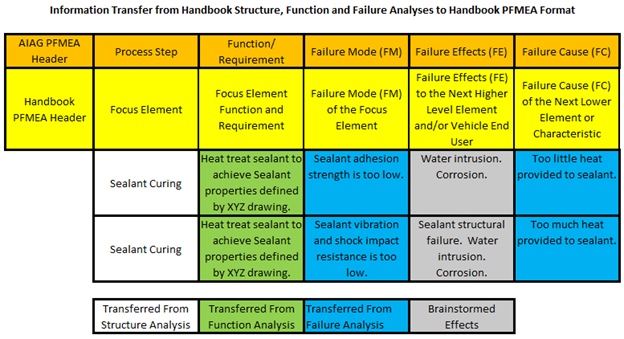
Following is information that is used to manage process risk that is common to both the AIAG-VDA PFMEA and AIAG 4th Edition PFMEA methods that is derived from the structure, function and failure analyses. The table shows the slight difference in terminology between the headers of the two PFMEA forms. When transferring information from the structure, failure and function analyses to the PFMEA, the following happens:
- the Process Step of the structure analysis becomes the “Focus Element”;
- the Process Step function of the function analysis becomes the “Focus Element Function and Requirement”;
- the Process Step failure of the Failure Analysis becomes the “Failure Mode of the Focus Element”;
- the Process Work Element failure of the Failure Analysis becomes the failure cause of the “Failure Mode of the Focus Element”.
- The effects of the “Focus Element Failure Mode” are brainstormed.
A review of the contents of the AIAG-VDA PFMEA reveals the following:
-
- The information provided by the Process Flow Diagram into the Structure and Function Analyses is placed in the PFMEA columns in the same manner that it would have been if the information was transferred directly to the PFMEA from the Process Flow Diagram as it is done when using the AIAG 4th Edition PFMEA methodology.
- Page 83 of the AIAG-VDA FMEA Handbook defines one of the main objectives of the Failure Analysis that is used to construct the PFMEA as the “establishment of the failure for each function”. In the case of the Curing Oven the function is to apply heat to sealant. Failures of the process step would be to apply too little or too much heat to the sealant. In the proposed AIAG-VDA Handbook PFMEA method, these two failures become failure causes in the PFMEA. The problem is they are not root causes. They describe how the process step fails and not why the process step fails. Without knowing the root causes of why the process step failed, a prevention control cannot be defined nor can the PFMEA line be used for risk management.
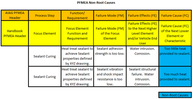
- Some people use the Ishikawa diagram to define failure causes when creating a PFMEA using the AIAG 4th Edition PFMEA methodology. Unlike the proposed AIAG-VDA PFMEA methodology, the Ishikawa Diagram allows the user to directly identify failure causes without the need to define functions for the cause category that the causes fall under. When using the Ishikawa diagram, one continues ask questions until a root cause is found. If one were using an Ishikawa diagram to determine the root cause in the example provided, the first question that would be asked is “What can the Curing Oven do to cause the Sealant Adhesion strength to be too low?”. The second question ask would be “Why did the Curing Oven provide too little heat to the sealant”. One answer would be “The Curing Oven Program Temperature Setting is too low” which is a root cause. The proposed AIAG-VDA Handbook PFMEA methodology has no space in the Excel spreadsheet to answer the second question thus you are left with a non-root cause provided by the answer to the first question.
Conclusion
It is difficult to define one benefit of using the Structure, Function and Failure Analyses that is being proposed by the AIAG-VDA PFMEA methodology to populate the PFMEA form. The use of the Structure and Function analysis to populate the Process Step and Function/Requirement PFMEA columns forces the user to place the information in a Structure and Function Analysis so it can be used to populate the two columns rather than allowing the person performing the PFMEA to place it there directly. The proposed PFMEA methodology also forces the performer of the PFMEA to define functions for the Ishikawa Cause Categories to define the PFMEA failure causes when the inventor of the Ishikawa Diagram, Mr. Kaoru Ishikawa, did not believe such a step is necessary. To make matters worse, when the step of defining functions for Process Work Elements is required and the failure cause becomes a description of how the function is not met, the Failure Cause entered into the PFMEA is most likely a non-root cause thus making the definition of a prevention control impossible and the line of the PFMEA useless for risk management.
If the AIAG-VDA PFMEA methodology, which uses structure, function and failure analyses to determine critical PFMEA content is implemented, it will result in an automotive PFMEA process that is both considerably less effective and more inefficient than the current methodology described in the AIAG 4th Edition FMEA Manual. A better path to standardization between VDA and AIAG Process FMEA methodologies is to accept the current AIAG 4th Edition Process FMEA methodology as the starting core methodology and make the necessary adjustments to it to arrive at a joint AIAG-VDA Process FMEA standard.
If you have any questions about anything in this article or other elements of the proposed AIAG-VDA FMEA Handbook, please feel free to contact the author. If you wish to provide comments to the AIAG about the proposed changes you can do so at the AIAG Quality Store.
About The Author

Richard Harpster
Richard Harpster is president of Harpco Systems, which he founded in 1987. Harpco Systems specializes in providing software, training, and consulting for risked-based product lifecycle management (RBPLM). During the past 30 years, Harpster has helped hundreds of companies implement improved risk-based design and manufacturing systems in a wide variety of industries. He is a recognized expert in the application of FMEAs and has invented several new concepts, including the linking of design FMEAs to process FMEAs in 1990, which became an automotive industry standard 18 years later. His latest inventions in the field of RBPLM include Requirements Risk Assessment (RRA), Usage Risk Assessment (URA), Multiple Integrated Cause Analysis (MICA) and Rapid Integrated Problem Solving (RIPS). He has published several papers on the topic of RBPLM.
“Harpco breaks down the barriers and corrects the pitfalls so companies can reap the full benefits of FMEA. Classroom training not only properly teaches FMEA, but participants actually build their business’s FMEA as they go and are often blown away by how much work got accomplished. Harpco Systems has become known as the Modern FMEA for a reason. Its structured, simplified and sustainable.”
 Chris Follis, Regal Beloit Director of Quality
“We used QPlus to achieve Q1 and ISO 16949 successfully at the Ford Motor Co. Monroe BAO Plant. The software promoted linked documentation that prevented issues at internal and external audits. Assured the quality documents at the operations production level had all relevant and concurrent information that was reviewed in the program files. QPlus allowed the program members to create a baseline “Hot End Exhaust” database that produced linked documentation from the DFMEA to the production visual aids the operators used to perform correctly.”
 Chris Norton, Ford Engineering Manager
“Harpco’s training is first rate and helps develop new ways of thinking about the importance of creating proper specifications early. Separately, I’ve seen firsthand the effectiveness of using their approach in problem solving, helping to advance problems that had reached a stall using traditional methods.”
 Todd Gross, VP of Global Quality
“We were very fortunate to work with Rich Harpster and his team as we improved our DFMEA process at Calsonic. There is no better teacher, coach, implementer than Rich when it comes to creating a knowledge base for engineers to use in creating part specs to assure that products meet the customer’s requirements. Rich teaches the basics, then he accelerates the FMEA process so that requirements and specs are related in a database that can be continually updated.”
 Marv Beasley, Calsonic Director of Engineering
“I would like to thank Harpco Systems for the help, advice and frankly the education in how to design, develop, source and manufacture new to world products.”