

The Case Against the AIAG-VDA DFMEA – Part II
Introduction
On January 31, 2018 Quality Digest published “The Case Against the AIAG-VDA DFMEA”. The purpose of the paper was to provide proof that if implemented the proposed AIAG-VDA Handbook DFMEA methodology is considerably less effective and more inefficient than the existing AIAG 4th Edition DFMEA methodology. To make the concepts contained in the paper easy to understand, a simple example using a Twin Bed with a potential leg fracture issue was used.
The author received comments that the Twin Bed example did not prove anything because of its simplicity and/or the design risk issue covered. To respond to the comments, the author will use the “Throttle Positioner” product example found in the current VDA FMEA manual titled “VDA Product- and Process-FMEA Manual, 2nd Revised Edition 2006, updated in DFMEA June 2012” to prove the ineffectiveness and inefficiency of the proposed AIAG-VDA DFMEA methodology. For the remainder of the paper, this manual shall be referred to as the “2012 VDA Manual”.
Limitations of Throttle Positioner Example Found in VDA Manual
Unfortunately, the Throttle Positioner example found in the 2012 VDA manual is incomplete. The 2012 VDA Manual does not develop the Failure Analysis (2012 VDA Manual Figure 2.8.3.1-1, page 40) for all the branches of the Throttle Positioner Structure Analysis (2012 VDA Manual Figure 2.8.1.1-2, page 36) and Function Analysis (2012 VDA Manual Figure 2.8.2.1-1, page 38). If the instructions for the creation of the VDA DFMEA found in the 2012 VDA Manual are properly followed, four different DFMEAs are required (Throttle Positioner, Transmission, Primary Gear, Primary Gear Axis). The 2012 VDA Manual provides only two entries of the Primary Gear DFMEA while providing nothing on the other three DFMEAs.
Because of limitations on the information in the 2012 VDA Manual, the following steps will be taken:
- The paper will be limited to developing Design FMEA entries only for the entries found in the Throttle Positioner Failure Analysis.
- Since a DFMEA does not exist in the 2012 VDA Manual for the Throttle Positioner element, the effects for the Throttle Positioner failure (“Air opening not enlarged despite actuation”) found in the Failure Analysis will be derived from the Primary Gear DFMEA and Severity Ratings table (2012 VDA Manual A4.1, page 117).
- Prevention and Detection controls for non-existent DFMEAs will be listed as TBD (To Be Determined).
- All Occurrence ratings are set to 1 except for those defined in the Primary Gear DFMEA found in the 2012 VDA Manual.
Required Information in DFMEA to Manage Risk
The primary task of the design engineer is to create a set of Product Design Specifications that define a product that will meet the Product Design Requirements. The Product Design Specifications contain the information required for manufacturing to build the product. They include dimensional and material specifications as well as required software code if applicable. Due to the wide variety of Product Design Requirements a product might have and the fact that some of the Product Design Requirements can be competing, it is often impossible for the design engineer to define Product Design Specifications that define a product which will meet all the Product Design Requirements all the time. All designs have risk when they are released for manufacture.
When done properly, the DFMEA is a structured risk assessment of the adequacy of the Product Design Specifications in defining a product that will meet the Product Design Requirements. It enables the design engineer to identify the product failures that can occur and the Product Design Specifications that control whether the failures will happen. When properly performed, the Design FMEA allows the design engineer to identify the Product Design Specifications that must be risk optimized to reduce the design risk to a level that is acceptable to both the customer and company.
For a line of a DFMEA to be used to manage risk, two conditions must be present. First, the Product Design Requirement placed in the Requirement column and the failure mode must be verifiable. Secondly, the entry in the Failure Cause column of each line of the DFMEA must contain a Product Design Specification condition that may be causing the Failure Mode. The Product Design Specification condition is known as the potential “root cause” of risk exposure defined by the DFMEA line.
Using the Proposed AIAG-VDA Handbook DFMEA Methodology to Manage Risk
In the Handbook DFMEA Method, the Design Requirements, Failure Modes, Effects and Causes are not entered directly into the DFMEA. They are derived from a Structure Analysis, Function Analysis and Failure Analysis.
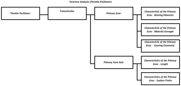
The first step is to create a Structure Analysis. When constructing the Structure Analysis, the Assembly, Sub-Assembly(s) and Component(s) are known as elements. The parent-child relationships between the elements are shown graphically. The characteristics of the components that control the Components performance are also shown. Following is the Structure Analysis for the Throttle Positioner found in the 2012 VDA Manual (Note: Only elements referenced in the Failure Analysis (2012 VDA Manual Figure 2.8.3.1-1, page 40) are shown).
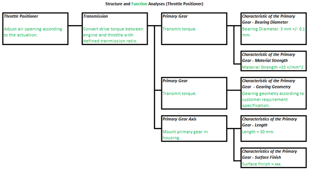
The next step is to create a Function Analysis. The Function Analysis is created by defining the Design Functions/Requirements for the Assembly, Sub-assembly(s) and Component(s) of the Structure Analysis. Specifications for the Characteristics of the Structure Analysis are provided.
Following is the Function Analysis for the Throttle Positioner Structure Analysis found in the 2012 VDA Manual (Note: Only elements referenced in the Failure Analysis (2012 VDA Manual Figure 2.8.3.1-1, page 40) are shown).
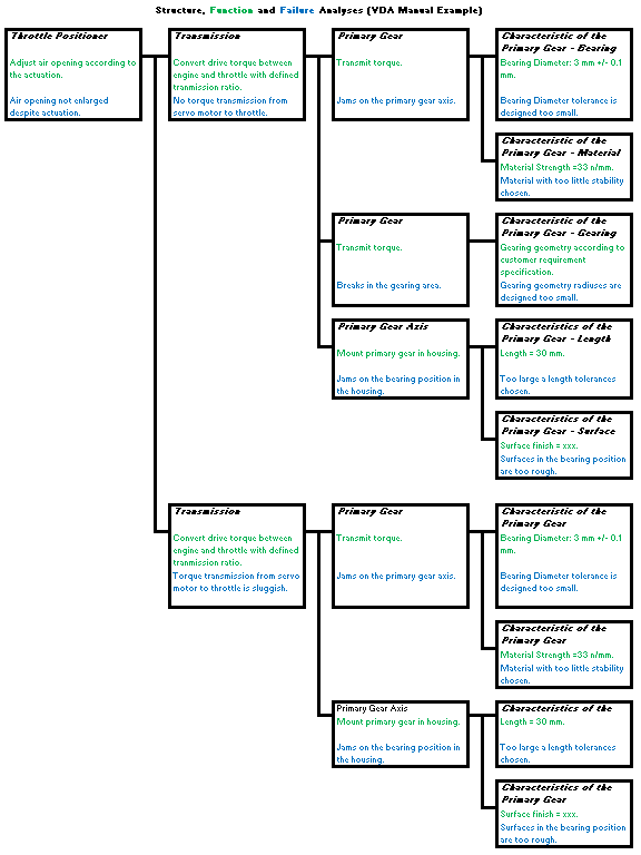
Once the Function Analysis has been created the next step is to construct the Failure Analysis. The Function Analysis is created by defining the failures for the functions of the Assembly, Sub-assembly(s) and Component(s) of the Function Analysis. When constructing the Failure Analysis, each failure must be described in terms of the level at which it occurs. Objectionable condition(s) of the Characteristics that could lead to the component failure are provided.
Following is the Failure Analysis for the Throttle Positioner Structure Analysis found in the 2012 VDA Manual (2012 VDA Manual Figure 2.8.3.1-1, page 40).
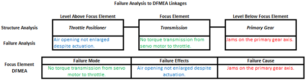
A DFMEA is created for the Assembly and each of the Sub-assemblies and Components of the Structure Analysis. The Assembly, Sub-assembly or Component that the DFMEA is being performed on is known as the Focus Element of the DFMEA. The Requirements for each Focus Element DFMEA are taken from the Function Analysis. The Failure Analysis is used to populate the Failure Modes, Failure Effects and Failure Causes of the Focus Element DFMEAs. The Failure of the Focus Element becomes the DFMEA Failure Mode. The failure of the element above the focus element becomes the DFMEA Failure Effect. The failure of the element below the focus element becomes the DFMEA Failure Cause.
Following is the DFMEA for the Throttle Positioner that is derived from the Function and Failure Analysis in the 2012 VDA Manual.
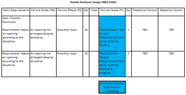
Both Failure Causes in the Throttle Positioner DFMEA do not specify a potential issue with a product design specification and thus are non-root causes. Consequently, neither of the two lines of the DFMEA can be used to manage design risk. The presence of not root causes in DFMEAs generated using the VDA Failure Analysis is very common.
Following are the DFMEA entries for the Transmission DFMEA that are derived from the Function and Failure Analysis in the 2012 VDA Manual.
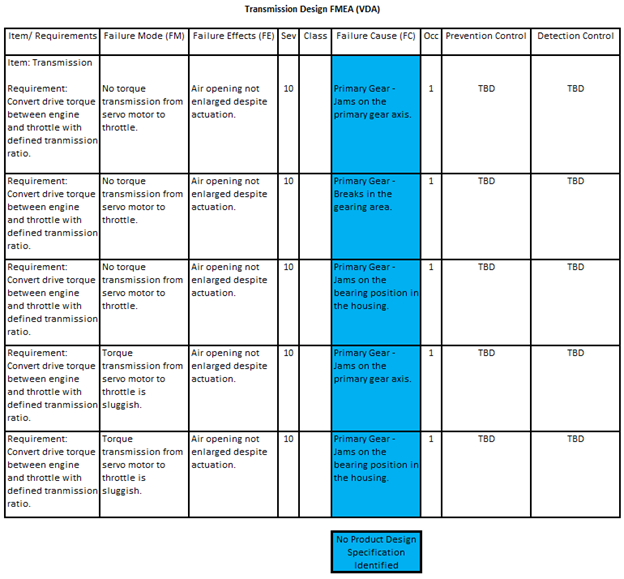
Like the Throttle Positioner DFMEA, all the failure causes in the DFMEA do not specify a potential issue with a product design specification and thus are non-root causes. Consequently, none of the lines of the Transmission DFMEA can be used to manage design risk.
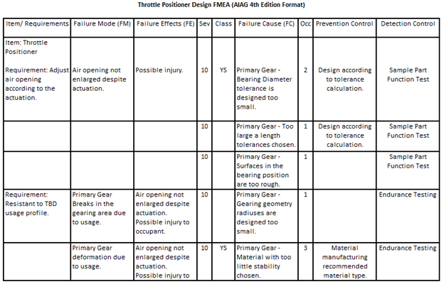
Following are the DFMEA entries for the Primary Gear that are derived from the Function and Failure Analysis in the 2012 VDA Manual.
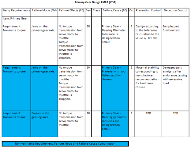
The first line of the Primary Gear DFMEA can be used to manage design risk. The product design requirement and failure mode combination is verifiable and the Failure Cause identifies a product design specification that controls whether or not the failure mode occurs.
Problems exist in lines two and three. Based on the Prevention and Detection Controls identified for the second line, there appears to be a concern that physical changes to the Primary Gear can occur due to one or more usage conditions thus resulting in the Primary Gear jamming on the Primary Gear. However, the design requirement states only “Transmit torque” and provides no information on the usage condition(s) that may be causing the Primary Gear physical change leading to the Primary Gear jam. Consequently, one would not know what load to provide to the material manufacturer or how to construct the endurance testing described in the Prevention and Detection Controls columns.
Although the Primary Gear “Breaks in the gearing area” failure mode is not covered in the DFMEA example provided in the 2012 DFMEA manual, one could assume the same endurance testing would also be done to evaluate the possibility of Primary Gear structural failure. Since one cannot properly define the loads for the Prevention and Detection Controls, neither line 2 or 3 can be used for design risk management.
Following are the DFMEA entries for the Primary Gear Axis that are derived from the Function and Failure Analysis in the 2012 VDA Manual.
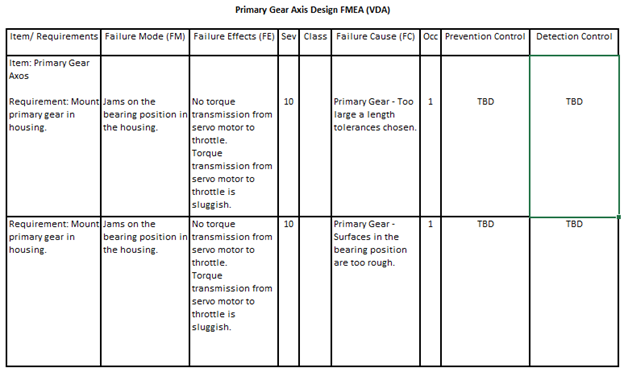
Both lines of the Primary Gear Axis DFMEA can be used for design risk management. Although the example DFMEA found in the 2012 VDA Manual does not include the two lines, it would be quite easy to define the Prevention and Detection Controls due to the Requirement and Failure Mode entries being verifiable and the Failure Causes being root causes.
Using the AIAG DFMEA Method to Manage Risk
Following is a properly constructed DFMEA using the AIAG 4th Edition DFMEA Method that captures all the information in the four DFMEAs created above.
A properly constructed DFMEA should never include a physical change of the product such as the Primary Gear breaking in the gearing area or Primary Gear deformation should never be entered as a DFMEA Failure Cause. Sometimes referred to as “mechanisms of failure”, these physical changes are failures to survive a condition of usage and consequently are Failure Modes.
Unfortunately, the mistake of using a “mechanism of failure” as a Failure Cause is allowed by the AIAG 4th Edition FMEA Manual. As stated in the previous article, the DFMEA method described in the AIAG 4th Edition FMEA is not optimized and requires a few changes. Not allowing the use of a “mechanism of failure” as a Failure Cause is one of the changes that should be made.
The good news is that all five lines of the DFMEA created using the AIAG 4th Edition DFMEA methodology can be used for design risk management.
Conclusion
The DFMEA constructed using the AIAG 4th Edition FMEA methodology which addresses the Throttle Positioner example consists of five lines. All the lines of the DFMEA can be used for design risk management.
When the proposed AIAG-VDA Handbook DFMEA method is used to construct DFMEAs which address the Throttle Positioner example found in the 2012 VDA Manual, the following must be created:
- Structure Analysis;
- Function Analysis;
- Failure Analysis;
- four DFMEAs with a total of twelve lines.
Of the twelve DFMEA lines found in the four DFMEAs created using the AIAG-VDA DFMEA method only 25% or three of the lines can be used for design risk management. Two of the resultant DFMEAs have no lines that can be used for design risk management.
It is clear the AIAG 4th Edition DFMEA methodology is both more effective and more efficient than the proposed AIAG-VDA Handbook DFMEA method. I recognize the fact that the European community is highly invested in the VDA methodology and there will be heavy resistance in giving it up. However, “FMEA Process Harmonization” should not be a reason for the US automotive industry to accept a DFMEA and PFMEA processes that are not as effective and efficient as the ones they already have.
If you have any questions about anything in this article or other elements of the proposed AIAG-VDA FMEA Handbook, please feel free to contact the author. If you wish to provide comments to the AIAG about the proposed changes you can do so at the AIAG Quality Store – https://www.aiag.org/store/publications/details?ProductCode=XO-FMEADRAFT.
About The Author

Richard Harpster
Richard Harpster is president of Harpco Systems, which he founded in 1987. Harpco Systems specializes in providing software, training, and consulting for risked-based product lifecycle management (RBPLM®). During the past 30 years, Harpster has helped hundreds of companies implement improved risk-based design and manufacturing systems in a wide variety of industries. He is a recognized expert in the application of FMEAs and has invented several new concepts, including the linking of design FMEAs to process FMEAs in 1990, which became an automotive industry standard 18 years later. His latest inventions in the field of RBPLM® include Requirements Risk Assessment (RRA®), Usage Risk Assessment (URA™), Multiple Integrated Cause Analysis (MICA™) and Rapid Integrated Problem Solving (RIPS®). He has published several papers on the topic of RBPLM®.“Harpco breaks down the barriers and corrects the pitfalls so companies can reap the full benefits of FMEA. Classroom training not only properly teaches FMEA, but participants actually build their business’s FMEA as they go and are often blown away by how much work got accomplished. Harpco Systems has become known as the Modern FMEA for a reason. Its structured, simplified and sustainable.”
 Chris Follis, Regal Beloit Director of Quality
“We used QPlus to achieve Q1 and ISO 16949 successfully at the Ford Motor Co. Monroe BAO Plant. The software promoted linked documentation that prevented issues at internal and external audits. Assured the quality documents at the operations production level had all relevant and concurrent information that was reviewed in the program files. QPlus allowed the program members to create a baseline “Hot End Exhaust” database that produced linked documentation from the DFMEA to the production visual aids the operators used to perform correctly.”
 Chris Norton, Ford Engineering Manager
“Harpco’s training is first rate and helps develop new ways of thinking about the importance of creating proper specifications early. Separately, I’ve seen firsthand the effectiveness of using their approach in problem solving, helping to advance problems that had reached a stall using traditional methods.”
 Todd Gross, Polaris VP of Global Quality
“We were very fortunate to work with Rich Harpster and his team as we improved our DFMEA process at Calsonic. There is no better teacher, coach, implementer than Rich when it comes to creating a knowledge base for engineers to use in creating part specs to assure that products meet the customer’s requirements. Rich teaches the basics, then he accelerates the FMEA process so that requirements and specs are related in a database that can be continually updated.”
 Marv Beasley, Calsonic Director of Engineering
“I would like to thank Harpco Systems for the help, advice and frankly the education in how to design, develop, source and manufacture new to world products.”