

The Case Against the AIAG-VDA DFMEA
Why this methodology should not be adopted
On Nov. 27, 2017, the Automotive Industry Action Group (AIAG) made a draft available of the co-developed AIAG-VDA FMEA Handbook for a 90-day stakeholder review and commenting period. The group who developed the handbook should be applauded for attempting to develop a standardized method for failure mode and effects analysis (FMEA) to replace the German Association of the Automotive Industry (VDA) and AIAG methodologies, and asking for public comment on the results of their efforts before its release.
Unfortunately, if adopted, the handbook’s proposed design FMEA (DFMEA) methodology will result in an implementation that is considerably less effective and much more inefficient than AIAG’s current methodology, found in its 4th Edition FMEA Manual. Although this article will provide general information on how the AIAG-VDA Handbook DFMEA and AIAG 4th Edition DFMEA methods work, it will not go deeply into the details.
The definition of risk
Risk has two components: the severity of harm when an objectionable incident occurs and the probable occurrence of the objectionable incident causing the harm. When managing risk in the design process, an objectionable incident occurs whenever a product design fails to meet a product design requirement.
Purpose of a design FMEA
The primary task of the design engineer is to create a set of specifications that define a product that will meet the product design requirements. The specifications contain the information required to build the product. They include dimensional and material specifications as well as required software code, if applicable. Due to the wide variety of product design requirements a product might have and the fact that some of the requirements can be competing, it is often impossible for the design engineer to define specifications that will meet all the product design requirements all the time. All designs have risk when they are released for manufacture.
When done properly, the DFMEA is a structured risk assessment of the adequacy of the product design specifications in defining a product that will meet the product design requirements. It enables the design engineer to identify the product failures that can occur and the specifications that control whether such failures will happen. When properly performed, the design FMEA allows the design engineer to identify the product design specifications that must be risk-optimized to reduce the design risk to a level that is acceptable to both the customer and company.
Example: Potential design failure requiring risk management
Following is a very simple example to explain how a properly performed DFMEA is used to manage risk. The product that is the focus of the example is a twin bed. The target life for the twin bed is 10 years. The twin bed is supposed to be able to withstand the forces of a 250-lb person getting into and out of the bed four times per day, which is a total of 14,600 entry and exit cycles over the target life of 10 years. There is a concern that the wooden legs might structurally fail due to occupant entry shock impacts over the bed’s lifetime due to the lower limit of wooden-leg diameter specification being too low. The company wishes to assess the risk of releasing the current twin bed design with the current wooden-leg diameter specification.
Using the AIAG DFMEA method to manage risk
Following is a properly constructed DFMEA using the AIAG 4th Edition DFMEA method that could be used to assess the risk of releasing the current wooden-leg diameter specification described above.
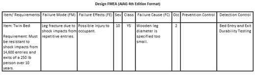
The job of the example DFMEA is to determine the risk of wooden-leg fracture due to releasing the current wooden-leg diameter specification to manufacturing. The concern is the lower limit of the specification may be too low. The DFMEA accomplishes the risk assessment in the following manner:
1. The verifiable design requirement that the DFMEA is assessing, the adequacy of the product design specification, is placed in the “Item/Requirements” column. (“Must be resistant to 14,600 entries and exits of a 250-lb person over 10 years.”)
2. The failure to meet the design requirement is defined in the “Failure Mode (FM)” column. (“Leg fracture due to shock impact from repetitive entries.”)
3. A description of the harm that can be experienced when the failure occurs is provided in the “Failure Effects (FE)” column. (“Possible injury to occupant.”)
4. A numerical rating is placed in the “Sev” (i.e., “Severity”) column, which corresponds to the severity of harm described in the “Failure Effects” column. (“10.”)
5. The product design specification whose adequacy is being assessed and the way it may have been mis-specified is entered in the “Failure Cause (FC)” column. (“Wooden-leg diameter is specified too small.”)
6. The method that will be used to determine the probability of the “Failure Mode” happening due to the “Failure Cause” are placed in the “Prevention” and “Detection” controls column. (“Bed Entry and Exit Durability Testing.”)
7. A numerical rating equivalent to the probability determined by the “Prevention” and “Detection” controls, is placed in the “Occ” (i.e., “Occurrence) column. (“2”.)
8. The “Sev” and “Occ” are looked up in a risk matrix that has symbols corresponding to the level of risk indicated by the “Sev” and “Occ” ratings. The appropriate risk level symbol is placed in the “Class” column. (“YS.”)
Using the proposed handbook DFMEA methodology to manage risk
In the AIAG-VDA DFMEA method, the design requirements, failure modes, effects, and causes are not entered directly into the DFMEA as they are in the AIAG 4th Edition FMEA. They are derived from a structure analysis, function analysis, and failure analysis. As we will see, this proves to be much more inefficient.
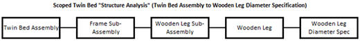
The first step is to create a structure analysis. For the example provided, one would create a structure analysis by creating a graphical representation of the literal description of the twin bed construction, including the wooden-leg diameter specification. The following is what the resultant structure analysis would look like.
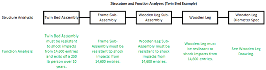
The next step is to create a function analysis, which is derived by defining the design functions/requirements for the assembly, subassemblies, and components of the structure analysis. Because we are performing a DFMEA to assess the risk of a specific product failure, the twin bed assembly function would be limited to “twin bed assembly must be resistant to shock impacts from 14,600 entries and exits of a 250-lb person over 10 years.”
The next step would be to define the design function/requirement. Because a portion of the shock seen at the mattress will be absorbed by the mattress and wooden-leg rubber wheels, a lower impact load will be seen by the frame subassembly. Determination of the impact of the mattress on the shock load seen by the frame subassembly could take considerable time and effort. The impact of the wooden-leg rubber wheels on the shock load on the frame subassembly is even more complex because changes in wheel dimensions and material type could result in the wheel absorbing different levels of shock, thus changing the design requirement.
For these two reasons, it would be extremely difficult and highly unlikely that the twin bed designer would attempt to define a verifiable shock-load resistance requirement at the frame subassembly level unless forced to define one to fulfill the need to populate a function analysis. If forced to define one, the most like entry would be something like “Frame subassembly must be resistant to shock impacts from 14,600 entries,” which is not verifiable.
Because we are unable to define a verifiable design function/requirement for the frame subassembly, it will also be impossible to define verifiable design function/requirements for the wooden-leg subassembly and wooden leg. Like the frame subassembly, the most likely design function/requirements that will be created are “wooden leg assembly must be resistant to shock impacts from 14,600 entries” and “wooden leg must be resistant to shock impacts from 14,600 entries,” neither of which are verifiable.
The function analysis for the example provided would look like the following:
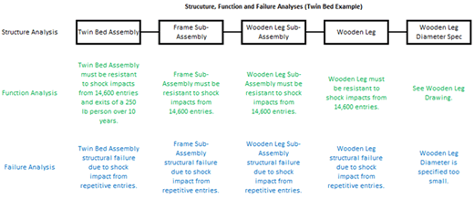
Once the function analysis has been created, the next step is to construct the failure analysis. When constructing the failure analysis, each failure must be described in terms of the level at which it occurs.
Keep in mind that the AIAG-VDA DFMEA method does not allow you to talk about structural failure of the wooden leg until you get to the wooden leg level in the analysis. So, in our example, the first failure would be at the twin bed assembly level. Because the failure must be defined in terms of the level at which the failure occurs, a failure entry for the twin bed assembly level would be “twin bed assembly structural failure due to shock impact from repetitive entries.”
Using the same logic, the second-level failure would be “frame subassembly structural failure due to shock impact from repetitive entries.” The third level failure would be “wooden leg subassembly structural failure due to shock impact from repetitive entries.” The fourth level would be “wooden leg structural failure due to shock impact from repetitive entries.” Finally, in the fifth level, we get to the product design specification issue we wish to investigate, which is the “wooden leg diameter is specified too small,” a result we got to much more quickly and efficiently in the AIAG 4th Edition FMEA.
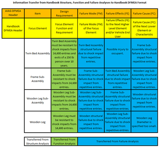
Following are the resultant structural, function, and failure analyses that will be used to construct the DFMEA.
The AIAG-VDA DFMEA form was developed to support the implementation of the structure analysis, function analysis, failure analysis, and DFMEA. Consequently, there is additional information in the handbook DFMEA form that is not found in the AIAG 4th Edition DFMEA form. This additional information is not needed to support the use of the DFMEA as a design risk management tool.
Following is information that is common to both the AIAG-VDA DFMEA and AIAG 4th Edition DFMEA methods and is derived from the structure, function, and failure analyses. The table shows the slight difference in terminology between the headers of the two methods.
Instead of the one DFMEA required to handle the issue with the AIAG 4th Edition DFMEA method, we now need four DFMEAs when using the proposed AIAG-VDA method. A review of the contents of the multiple AIAG-VDA DFMEAs reveals every design FMEA has a design function/requirement that is not verifiable or a failure cause that does not identify the product design spec that is being assessed. The presence of either of these conditions makes the line of the design FMEA that they occur on ineffective for managing risk. Two of the four DFMEAs generated using this method have both conditions present.
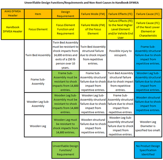
It is not uncommon when reviewing DFMEAs created using a DFMEA methodology that populates using the structure, function, and failure analysis (i.e., the AIAG-VDA DFMEA methodology) to find that every line of every DFMEA either contains a design function/requirement that is not verifiable or a failure cause that does not identify a product design specification that may have been improperly specified.
Conclusion
If the AIAG-VDA DFMEA methodology (which uses structure, function, and failure analyses to determine critical DFMEA content) is implemented, it will result in an automotive DFMEA process that is both considerably less effective and much more inefficient than the current methodology described in the AIAG 4th Edition FMEA manual. A better path to standardization between VDA and AIAG design FMEA methodologies is to accept the current AIAG 4th Edition DFMEA methodology as the starting core methodology and make the necessary adjustments to it to arrive at a joint AIAG-VDA DFMEA standard.
Given the large number of companies already using the structure, function, and failure analysis to create the content of their DFMEAs, this article is sure to be met with a lot of resistance. If you have any questions about anything in this article or other elements of the proposed AIAG-VDA FMEA Handbook, please feel free to contact the author. If you wish to provide comments to the AIAG about the proposed changes you can do so at the AIAG Quality Store.
About The Author

Richard Harpster
Richard Harpster is president of Harpco Systems, which he founded in 1987. Harpco Systems specializes in providing software, training, and consulting for risked-based product lifecycle management (RBPLM®). During the past 30 years, Harpster has helped hundreds of companies implement improved risk-based design and manufacturing systems in a wide variety of industries. He is a recognized expert in the application of FMEAs and has invented several new concepts, including the linking of design FMEAs to process FMEAs in 1990, which became an automotive industry standard 18 years later. His latest inventions in the field of RBPLM® include Requirements Risk Assessment (RRA®), Usage Risk Assessment (URA™), Multiple Integrated Cause Analysis (MICA™) and Rapid Integrated Problem Solving (RIPS®). He has published several papers on the topic of RBPLM®.“Harpco breaks down the barriers and corrects the pitfalls so companies can reap the full benefits of FMEA. Classroom training not only properly teaches FMEA, but participants actually build their business’s FMEA as they go and are often blown away by how much work got accomplished. Harpco Systems has become known as the Modern FMEA for a reason. Its structured, simplified and sustainable.”
 Chris Follis, Regal Beloit Director of Quality
“We used QPlus to achieve Q1 and ISO 16949 successfully at the Ford Motor Co. Monroe BAO Plant. The software promoted linked documentation that prevented issues at internal and external audits. Assured the quality documents at the operations production level had all relevant and concurrent information that was reviewed in the program files. QPlus allowed the program members to create a baseline “Hot End Exhaust” database that produced linked documentation from the DFMEA to the production visual aids the operators used to perform correctly.”
 Chris Norton, Ford Engineering Manager
“Harpco’s training is first rate and helps develop new ways of thinking about the importance of creating proper specifications early. Separately, I’ve seen firsthand the effectiveness of using their approach in problem solving, helping to advance problems that had reached a stall using traditional methods.”
 Todd Gross, VP of Global Quality
“We were very fortunate to work with Rich Harpster and his team as we improved our DFMEA process at Calsonic. There is no better teacher, coach, implementer than Rich when it comes to creating a knowledge base for engineers to use in creating part specs to assure that products meet the customer’s requirements. Rich teaches the basics, then he accelerates the FMEA process so that requirements and specs are related in a database that can be continually updated.”
 Marv Beasley, Calsonic Director of Engineering
“I would like to thank Harpco Systems for the help, advice and frankly the education in how to design, develop, source and manufacture new to world products.”